Buckling Analysis
PLII+
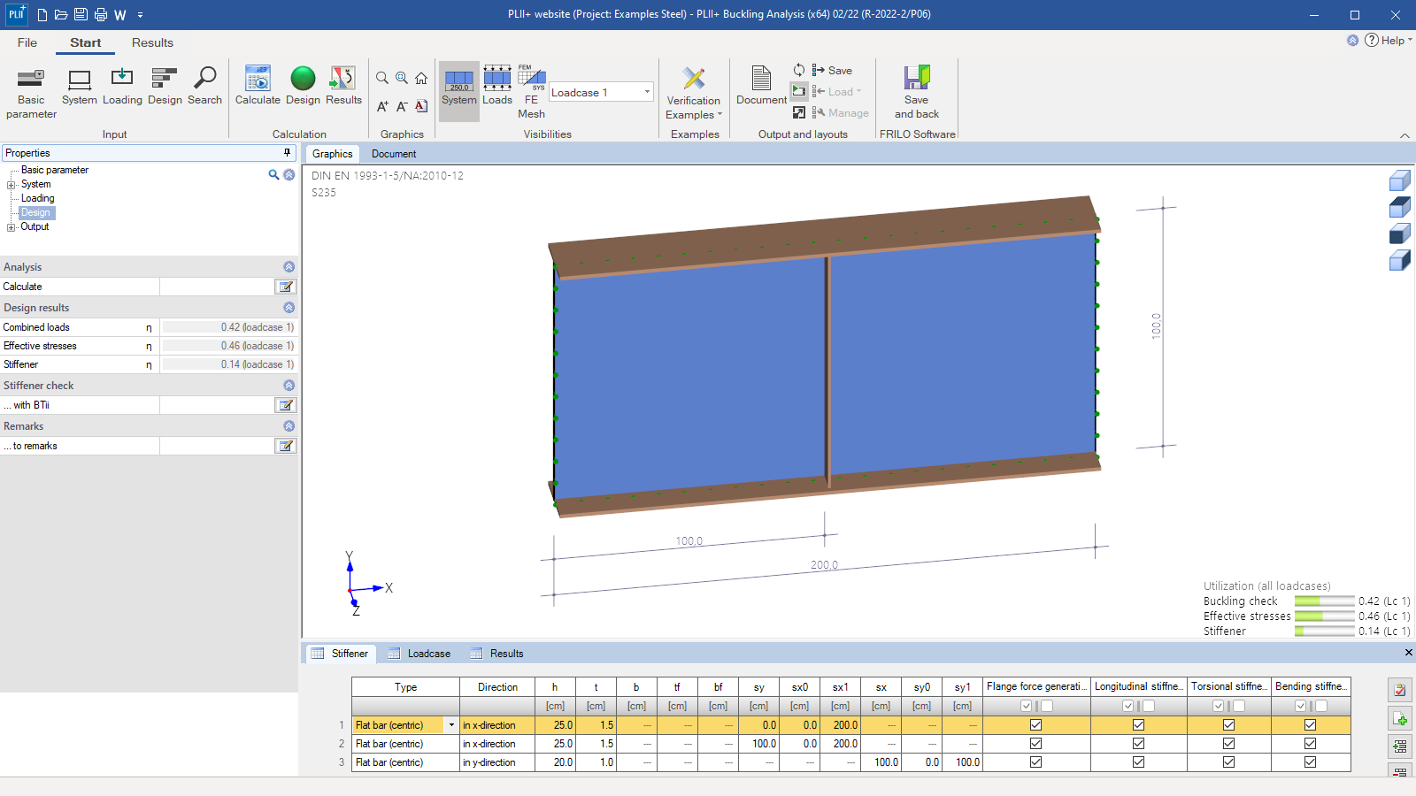
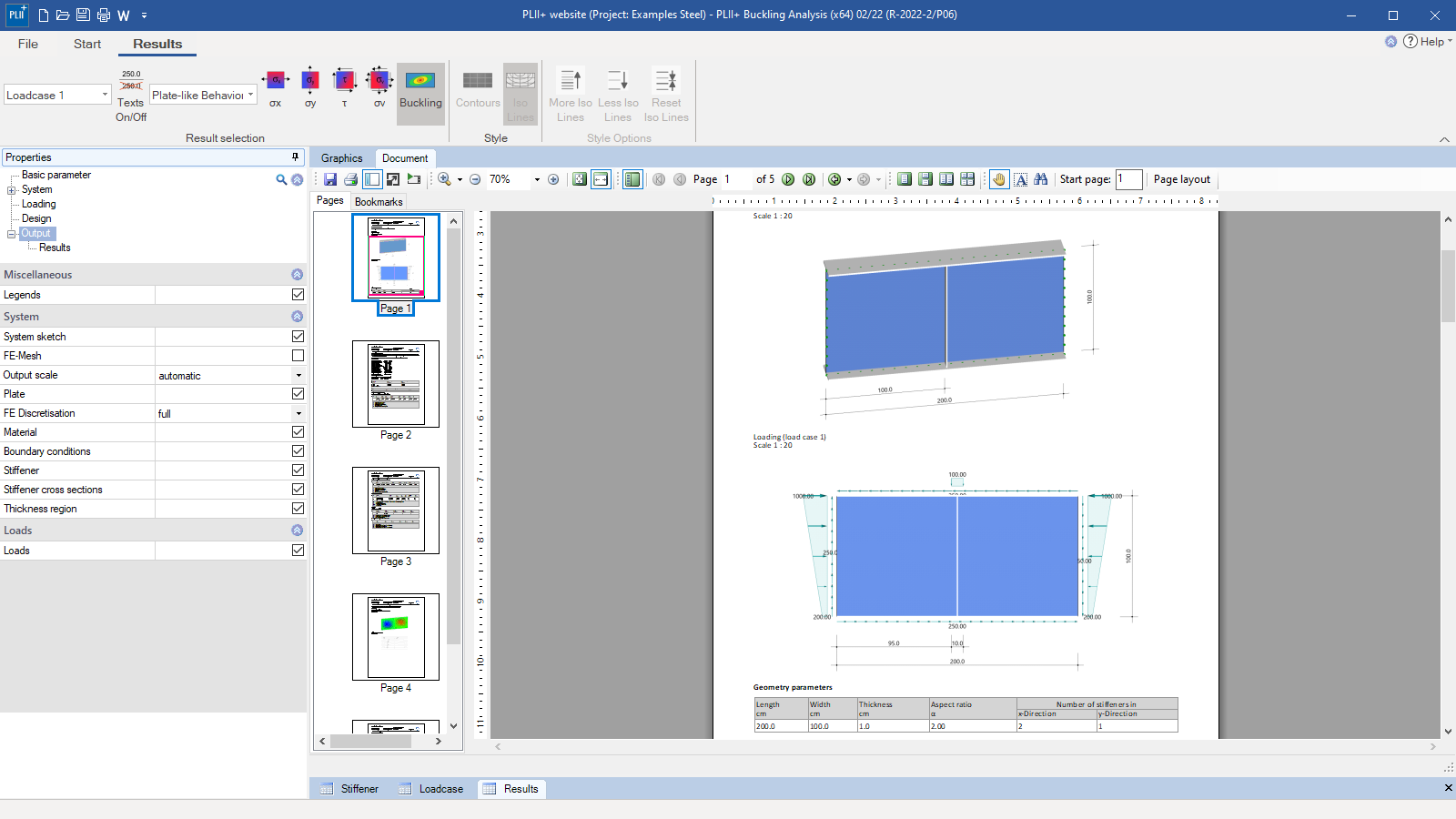
PLII+ is a calculation program for the analysis of rectangular plates with or without bracing that are exposed to user-defined actions on the edges. PLII+ is especially suitable for the verification of the buckling safety of welded beams with very slender webs.
Discover now more programs from the section Steel!
SHOW MOREMaterial
- Structural steel: S235, S275, S355, S450
- Annealed steel (S275N – S460N)
- Thermo-steel (S275M – S460M)
- Weathering steel (S235W – S355W)
- High-temperature steel (S460Q – S460QL1)
- Hollow section, hot-finished (S235H – S355H)
- Hollow section, hot-finished, fine-grain (S275NH – S460NH)
- User-defined steel
Structural system
- Braced and unbraced rectangular plates
Cross-sections:
- Plate with constant thickness t
- Arrangement of any number of horizontal and vertical buckling stiffeners (flat steel arranged centrically or eccentrically, angular bracing, T-bracing and trapezoidal bracing)
Supports:
The supporting conditions at the four plate edges are freely selectable. The user can define the plate edges as being free, pinned or restrained.
Loads
PLII+ allows the calculation of any number of load cases within the same item, including the following types of loads:
- Identical trapezoidal line loads applying opposite to each other at the transverse edges
- Identical trapezoidal line loads applying opposite to each other at the longitudinal edges
- Two concentrated loads (e.g. wheel loads from crane operation) applying at the upper edge of the area under buckling stress
- A freely definable reaction force applying at the bottom edge of the area under buckling stress, e.g. supporting force from a bearing corbel
- Constant circumferential edge shear load
The loading described in items 3 and 4 allows the user to map also variable bending and shear stress distributions in the area under buckling stress by calculating the plate loading on a cantilever or a single- or double-span beam pinned on two sides.
Design
The PLII+ program performs structural safety verifications as per EN 1993-1-5, section 10 (method of reduced stresses) and takes the regulations of the National Annexes into account. Besides the verification of the structural safety, the user can merely calculate the buckling load factors and buckling coefficients in accordance with the linear buckling theory. The calculation of the area under buckling stress is based on the Finite Element Method (FEM) in this analysis.
All examinations, including the calculation of the ideal buckling values, are performed on the entire area under buckling stress and include discrete longitudinal and transverse stiffeners. The effect of the stiffeners on the buckling behaviour is taken into account in all of these examinations. Therefore, verifications for an individual or partial area under buckling stress or an additional verification of the minimum stiffness of stiffeners can be dispensed with. Buckling on a member that behaves like an Eulerian column can also be considered for the entire braced area under buckling stress, if applicable.
Document file formats
- Word
- Printer
Output
Output profiles:
- User-defined output scope (tables and graphics)
Result graphics:
- System graphic
- FE mesh
- Load graphics
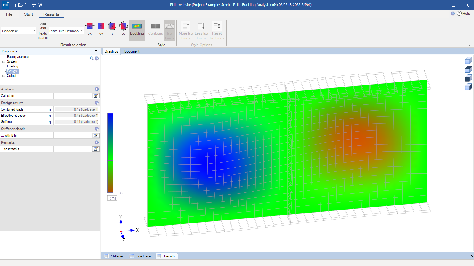
- Buckling mode
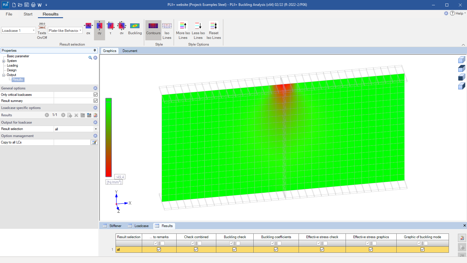
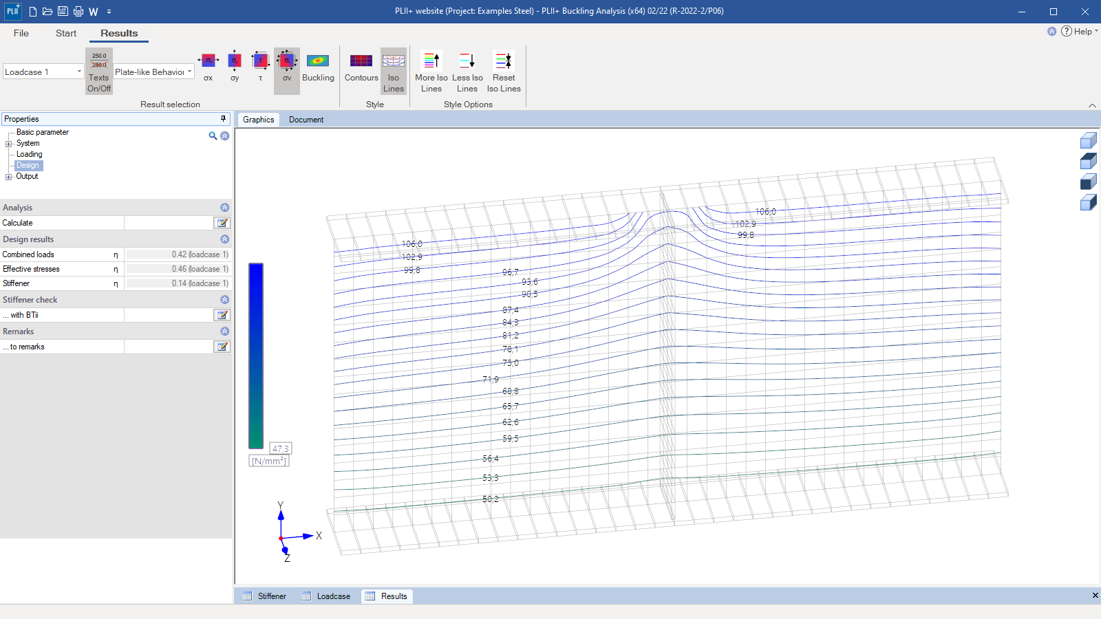
- Graphic showing the equivalent stress
Import options
- ASCII-file
Export options
- Word
- ASCII-file
Steel construction
- EN 1993-1-5
- DIN EN 1993-1-5
- ÖNORM EN 1993-1-5
- BS EN 1993-1-5
- DIN 18800
News
FRILO launches version 2024-2 with powerful updates for structural analysis and design
Highlights include the optimised design of Schöck Isokörbe®, the advanced integration of DC foundation engineering programs into the FRILO environment and new RSX interfaces for detail verifications in steel construction.

Load determination for eight-floor perimeter block development with FRILO Building Model
Find out how the structural engineers at bauart Konstruktions GmbH determined the loads for an eight-floor perimeter block development in Frankfurt’s Europaviertel district using the GEO from FRILO.

