FRILO
2024-2
All updates and new features in FRILO 2024-2
FRILO 2024-2 boasts numerous new features and program updates in the areas of solid construction, timber construction, steel construction, foundation engineering, BIM and Document Designer. These include:
- Determining utilization factors in fire incidents for masonry walls
- Lateral reinforcement of timber beams using flat steel profiles in HTV+
- New interfaces in RSX for detail verifications in steel construction
- New pile systems grouted micropiles & pipe grouted piles in Pfahl+
- Design the Schöck Isokorb® thermal insulation with more leeway in PLT
- Design single-sided plate beams (L-beams) for all flange positions in DLT+
- Note editor for FRILO and DC items in FDD
- Integration of DC items in FCC and FDD


Solid Construction

Timber

Steel & RSX

Foundation Engineering

GEO & FEM

DLT+

BIM-Connector

Document Designer
Prestressed Reinforced Concrete Girder B8
Designing recesses in girders
With FRILO 2024-2, users can now design recesses or openings in the girder in the FRILO program B8 Prestressed Reinforced Concrete Girder. To achieve this, the design processes of the German Committee for Reinforced Concrete specified in the booklets DAfStb-H. 399 and DAfStb-H. 599 have been implemented. The calculation results obtained are included in the output in tabular form. Optionally, users can also display the intermediate results in the comprehensive output version.
Strut-and-Tie Model Reinforced Concrete BSM+
Grid with freely definable width
To simplify the graphical input of geometries, openings, supports and loads in the Strut-and-Tie Model program BSM+, a grid with point snap has been implemented that users can display or hide. The width of the grid is customisable. In addition, the method of calculating user-defined strut-and-tie systems has been modified. For structural systems with fine meshing, the calculation is significantly faster. In order to better understand whether the compression and tension struts match the paths of the trajectories, the trajectories from the FE calculation can also be merged with the strut-and-tie model.
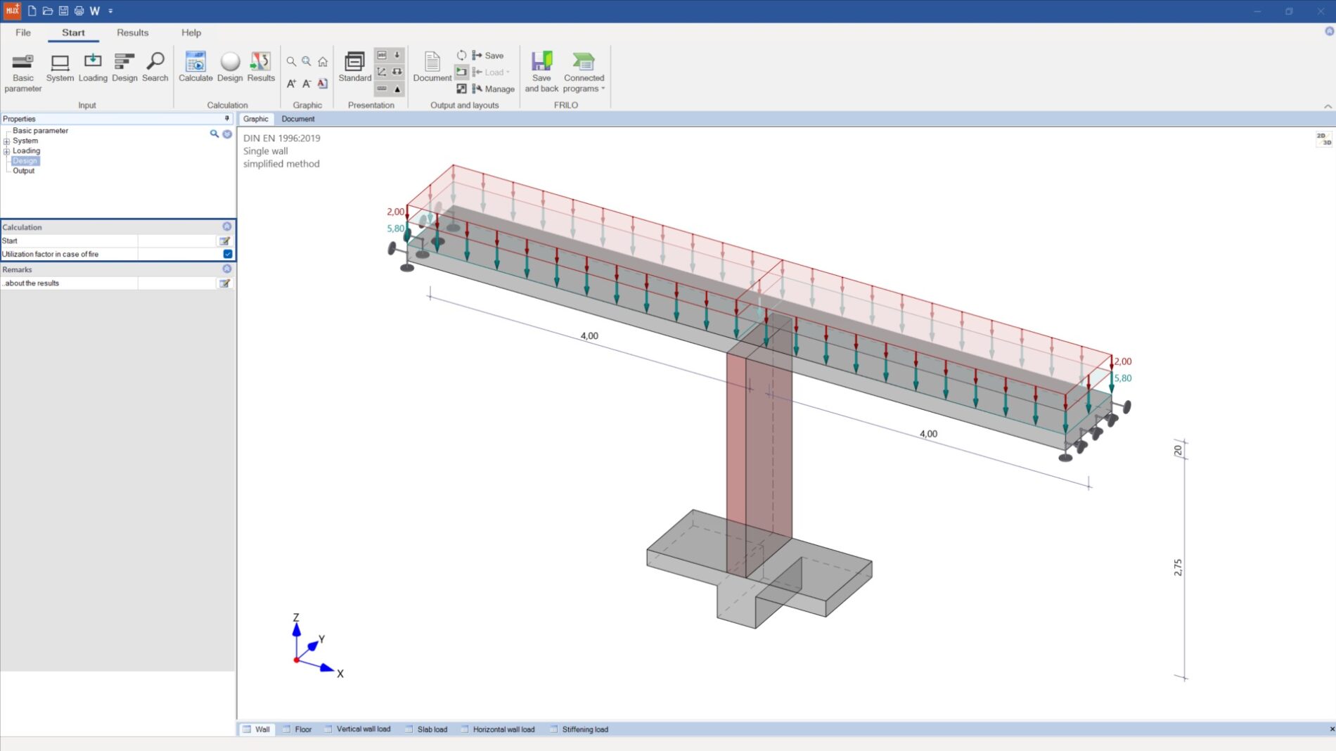
MWX+, MWM+, MWK+
Determining utilization factors in fire incidents
For masonry walls, users of the MWX+, MWM+ and MWK+ programs can determine the utilization factor (α6,fi or αfi) in fire incidents. Thanks to this factor, users can categorise the wall into fire resistance classes depending on the wall thickness by consulting the relevant standard. The resulting utilization factors are implemented in the output and can be used directly for the fire-safety analysis.
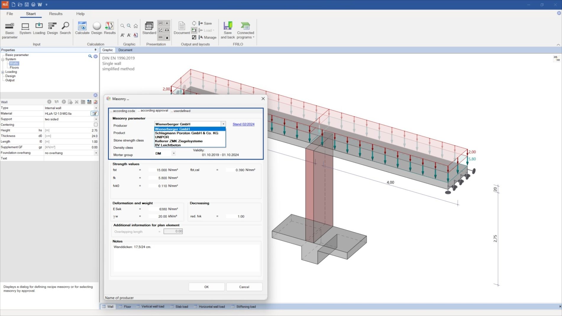
MWX+, MWM+, MWK+, MWP+
Updated approval information
With the 2024-2 update, the approval database for the products of Wienerberger GmbH, Schlagmann Poroton GmbH & Co. KG. and BV Leichtbeton has been updated to the latest state in all of the four masonry programs. With the provided approval information, a direct link to the approval of the respective manufacturer has been implemented. In addition, the validity of the approval is indicated both in the material dialog and in the output. Moreover, the user can now select whether the self-weight of the walls should be applied in full, with 50 % or not at all (except in MWM+).
Reinforced Timber Beam HTV+
Flat steel as a reinforcement
When the lateral reinforcement of timber beams is realised using steel cross-sections, a catalogue of different U-profile ranges and L-profile ranges was up to now available for selection in HTV+. In the FRILO 2024-2 version, users can upgrade timber beams also with flat steel profiles when using steel reinforcements. Because the profiles of the flat steel range are arranged horizontally as a standard (width x height), the user can rotate this type of reinforcement cross-section by 90° in the data-entry section of the system under “Reinforcement left” and “Reinforcement right”.
HTB+ and HNV+
Enter joints and spring stiffnesses
Until now, users could only define joints on the rigid supports in the programs Mechanically Jointed Beams HNV+ and Cross Laminated Timber Beams HTB+. The 2024-2 versions now allow additional joints to be entered at a user-defined point along the beam. Furthermore, users are now able to define spring stiffnesses and torsion spring stiffnesses for supports in addition to rigid supports. Furthermore, design verifications can now be performed in accordance with the Italian standard NTC EN 1995:2018 in HTB+ and HNV+.
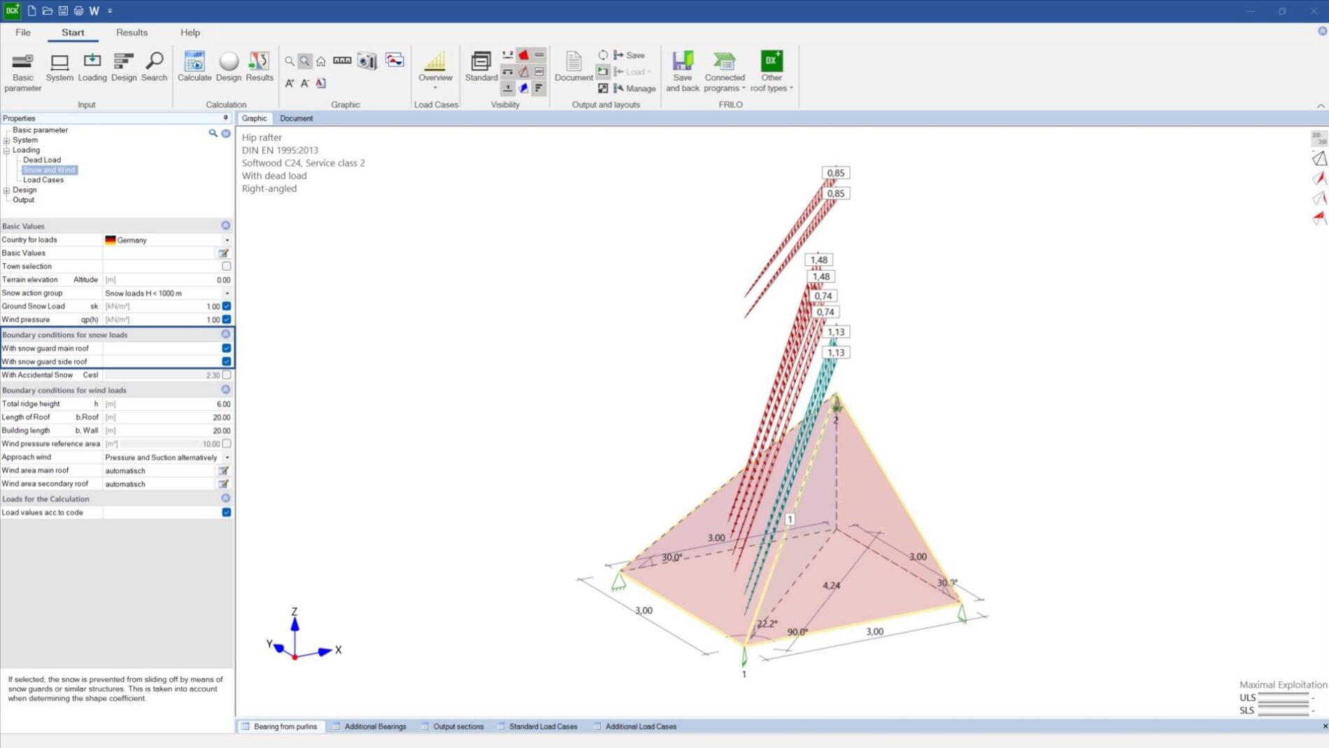
DGK+, DKD+, DPD+ and DSP+
Extensions in the roof programs
Thanks to the snow guard option (with µ option), users can activate the automatic application of snow loads from snow guards for the main roof and secondary roof in the Hip/Valley Rafter program DGK+. If users switch between hip rafters and valley rafters when working in DGK+, the cross-sections and loads can now be transferred in both directions in addition to the structural system. Users can disable the equivalent member verification on the cantilever arm not only in DGK+ but also in the other three roof programs DKD+, DPD+ and DSP+. In all four programs, users can specify user-defined output sections for the output of the internal forces.
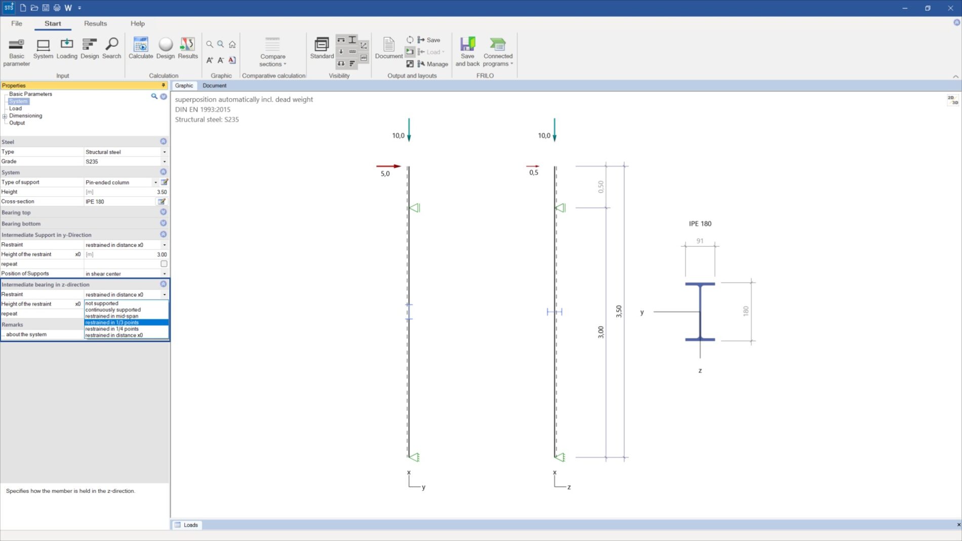
Single-span Steel Column STS+
Intermediate supports in the z-direction
Until now, users of the Single-span Steel Column program STS+ could only define intermediate supports in the y-direction (in the direction of the weak axis). With the updated FRILO 2024-2 version, they can also enter intermediate supports in the z-direction (in the direction of the strong axis). The following types of intermediate supports are available for selection: continuously supported, restrained in mid-span, restrained in third points, restrained in quarter points, restrained at distance x0. The extension allows users to fully map the entire structural system now.
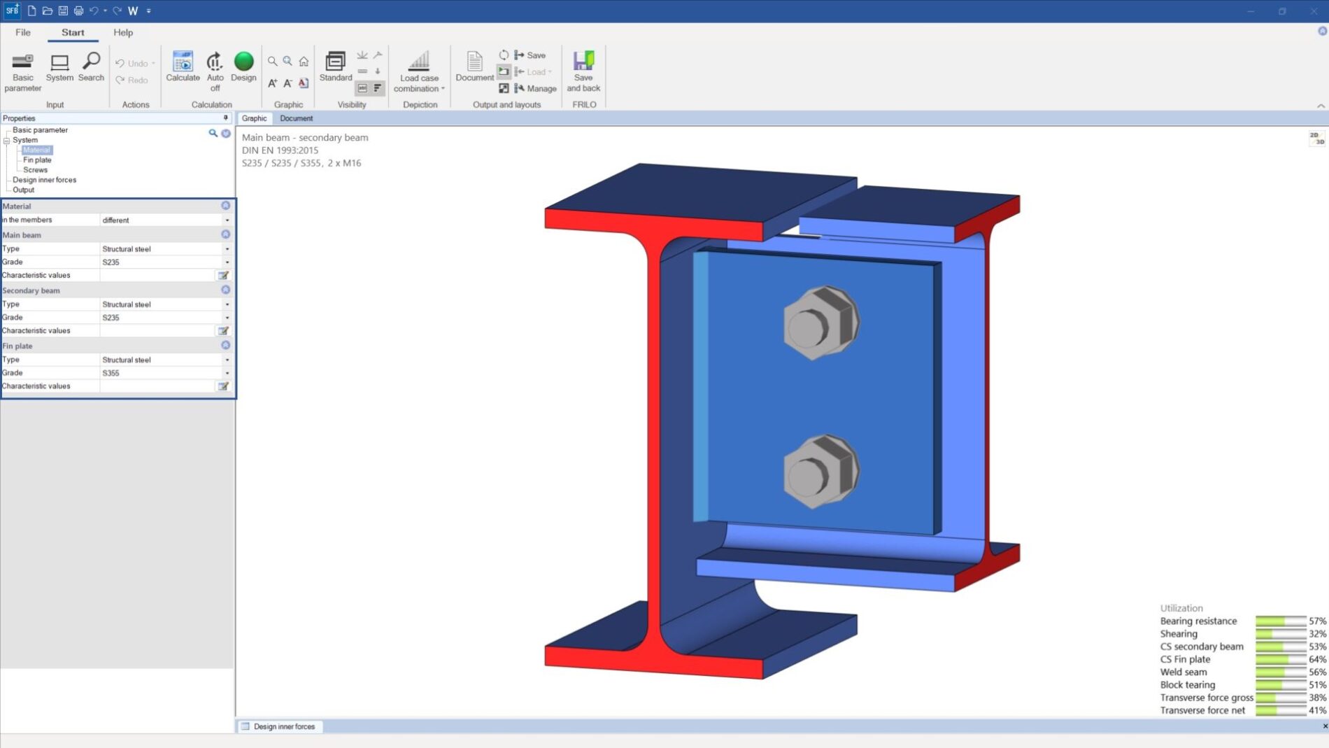
Fin Plate SFB+
Different steel grades for each component
In the Fin Plate program SFB+, users can choose between the two connection types “Column to secondary beam” and “Main beam to secondary beam” when entering a structural system. With the updated FRILO 2024-2 version, verifications can be performed on the defined structural system for the components column, main beam, secondary beam and fin plate depending on the different steel types and steel grades. For example, users can define structural steel grade S235 for the support and grade S355 for the secondary beam and the fin plate.
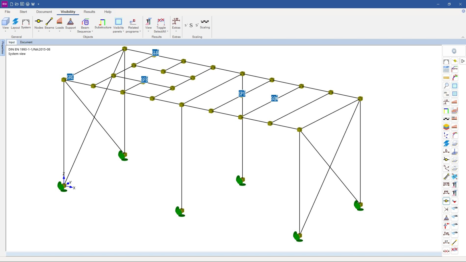
Framework RSX
New interfaces for detail verifications in steel construction
In version 2024-2 of the Framework program RSX, users can transfer internal forces, cross-sections and materials for the design of frame corners (SRE+), butt plate joints (SPS+), angle connections (SWA+) and fin plates (SFB+) to the respective FRILO programs. The transfer is limited to 2D internal forces. In addition, user-defined design sections can be created in RSX and transferred to SQN+ for graphical visualisation of the stress behaviour. For sets of members or individual members, users can transfer the structural system and its dimensions as well as the cross-section and the loads to DLT+.
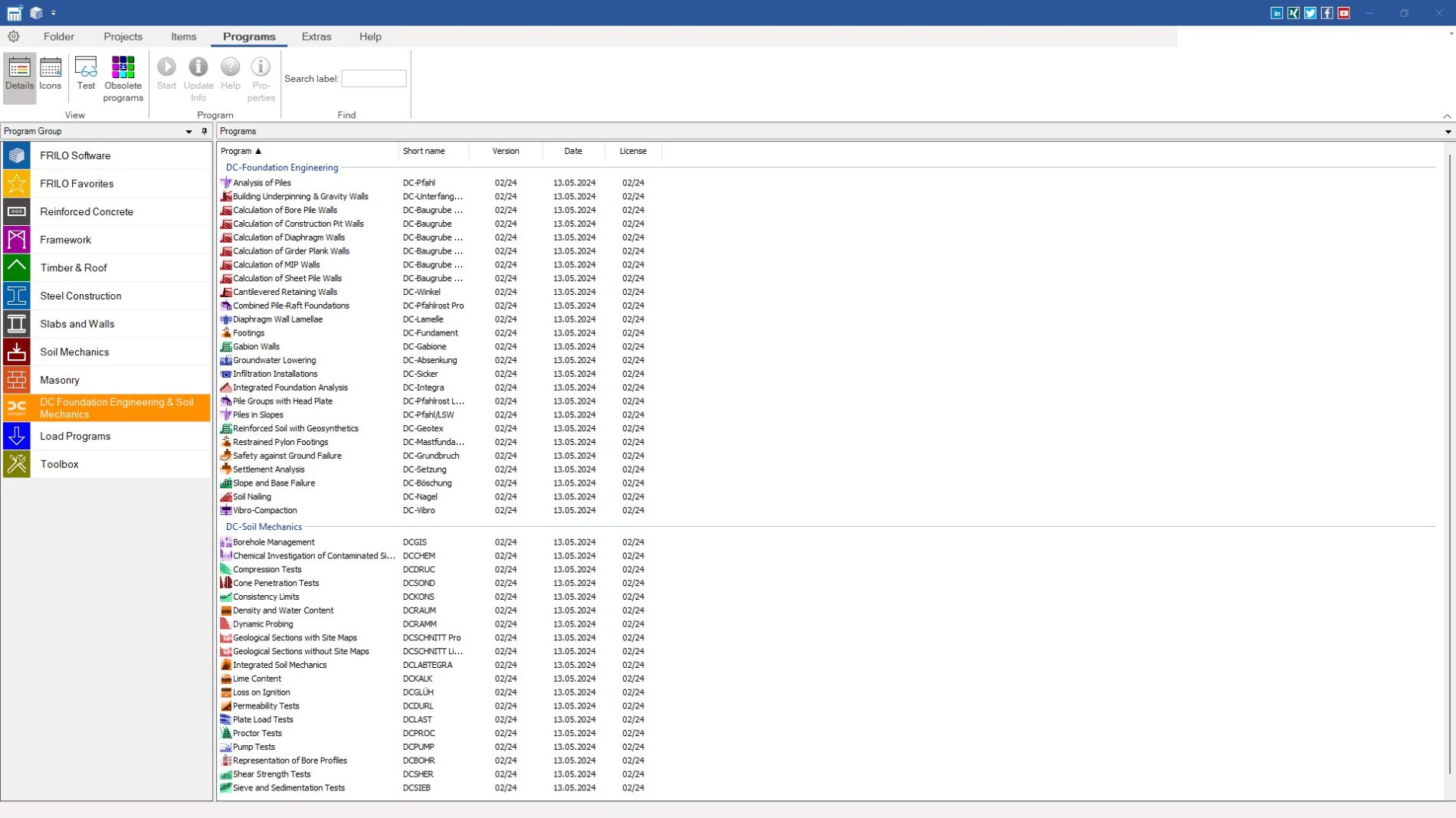
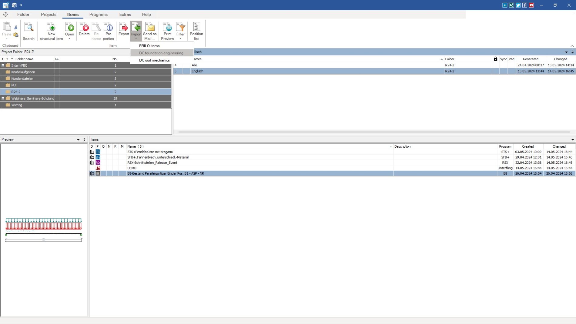
FRILO Control Center
Integration of the DC programs
Thanks to the integration of the DC software into the FRILO environment, the administration of all DC programs and items is now concentrated in a common data management system – the FRILO Control Center. The new feature also allows DC users to import existing DC items and projects into the Control Center. In addition, the integration of the installation of the DC programs into the FRILO Software (FSO) provides a common installation routine depending on the available licence file. Users no longer need to download and install DC programs separately.
Pile Foundation Pfahl+
Grouted micropiles & pipe grouted piles
With the 2024-2 update, the pile system in the Pile Foundation program Pfahl+ offers the user also grouted micropiles and pipe grouted piles for internal and external design. Another innovation: The buckling analysis can be performed as a stability verification according to Ofner and Wimmer for ductile driven piles, grouted micropiles and pipe grouted piles. Standardised hot-rolled and cold-rolled rectangular pipe sections in various geometries and wall thicknesses can now also be selected in the profile table for prefabricated drilled steel piles.
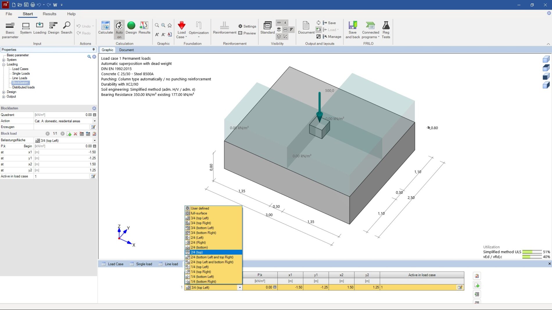
FD+, FDB+, GBR+
Defining block loads
Version 2024-2 of the FRILO programs FD+, FDB+ and GBR+ allows users to define block loads on a foundation, i. e. additional loads limited in both directions in the floor plan. The user can decide in which quadrants the loads are to be applied. In addition, the applied base pressure in the critical perimeter section can be determined from the integral of the proportional base pressure shape with possible consideration of a gaping joint in the punching shear analysis. Diagrams from various standards are now also available for calculating the permissible base pressure in the simplified verification for rock.
Slabs by Finite Elements PLT
Design the Schöck Isokorb® thermal insulation with more leeway
Users can now benefit from a new Schöck button in the PLT menu to call up the results for the Schöck Isokorb® thermal insulation. In the familiar dialog, the user now has the option of changing the Schöck Isokorb® insulation proposed by the program after the calculation. In addition to the graphical optimisation of the properties dialog, the Schöck Isokorb® types K-U and K-O with height offset as well as the type Z with load-bearing properties for cantilevered components were implemented in the PLT program. In the version 2024-2, users also have the option of neglecting small internal forces when designing the Schöck Isokorb® and displaying bar projections for collision planning. Furthermore, the structural-physical values were added to the output table of the Schöck Isokorb® element used.
Building Model GEO
Enhanced representation of the support reactions
Until now, the loads acting on a component were put out in the GEO Building Model as the sum of all support reactions (the sum of compressive and tensile forces). With the updated FRILO 2024-2 version, users can display both the sum of the support reactions for compressive forces alone and the sum of the support reactions for tensile forces alone in order to understand where tensile forces may be generated in the building and how the sum of all support reactions is made up. This way, users can quickly and easily find out whether any tensile or compressive forces are acting on a component and how high they are.
GEO & PLT
Define wall openings via two points
Until now, users of the programs GEO Building Model and PLT Slabs by Finite Elements could define wall openings only via the “Split wall” function by specifying exact dimensions and distance values. With the extension of the feature, they now can determine wall openings quickly and easily via two selected points on the wall axis. If required, the opening in the wall created via two points can also be filled with a lintel or parapet.
GEO, PLT & SCN
Enter free texts as graphical objects
Via the interactive graphical user interface, users can place any number of text elements on the graphic screen in the programs GEO Building Model, PLT Slabs by Finite Elements and SCN Walls by Finite Elements. Various functions are available to edit, copy, duplicate and move the text fields. Moreover, in the GEO output settings under “General”, users can also set whether the inserted text elements should only be displayed in the user interface or also in the output document or plot.
Reinforced Concrete Beam
Design single-sided plate beams (L-beams) for all flange positions
For the design of reinforced concrete beams, the cross-section database in the Continuous Beam program DLT+ has been extended to include L-beam cross-sections with the plate on top right, top left, bottom right or bottom left. Consequently, the height, web thickness, plate width and plate height can also be configured for L-beams in the cross-section dialog. Another innovation: In the system view, users can display the calculated effective plate width for single-sided (L) and double-sided (T) plate beams both in the user interface and the output document as a graphic.
Steel Beam
Connection to the Steel Cross-Sections program QS+
The FRILO program Steel Cross-Sections General QS+ allows users to create user-defined steel cross-sections deviating from the standard shapes and save them as a template. Thanks to the connection of QS+ to Continuous Beam DLT+, these user-defined steel cross-sections can now be taken into account when designing steel beams in DLT+. Items created in QS+ can be imported from current projects, folders or the entire FRILO database via the cross-section dialog and also edited in DLT+.
FRILO BIM-Connector FBC
Hiding and displaying nodes
The new version FRILO 2024-2 allows users to display and hide the start and end nodes or the corner nodes of the individual components in the BIM-Connector. This allows users to quickly and easily check where several nodes overlap, which indicates that components are not yet connected to each other.
FRILO BIM-Connector FBC
More information from SAF files
In the new FRILO 2024-2 version, the information content of SAF files that are imported into the BIM-Connector has been expanded. Thanks to the new features, the BIM-Connector can now evaluate information about the eccentricities of 2D components as a property of an SAF file. The export of SAF files has also been improved. Up to now, the focus when exporting data has been on the geometry of the building (components and materials); in future, SAF files will also contain information about the applied loads and the defined foundation areas.
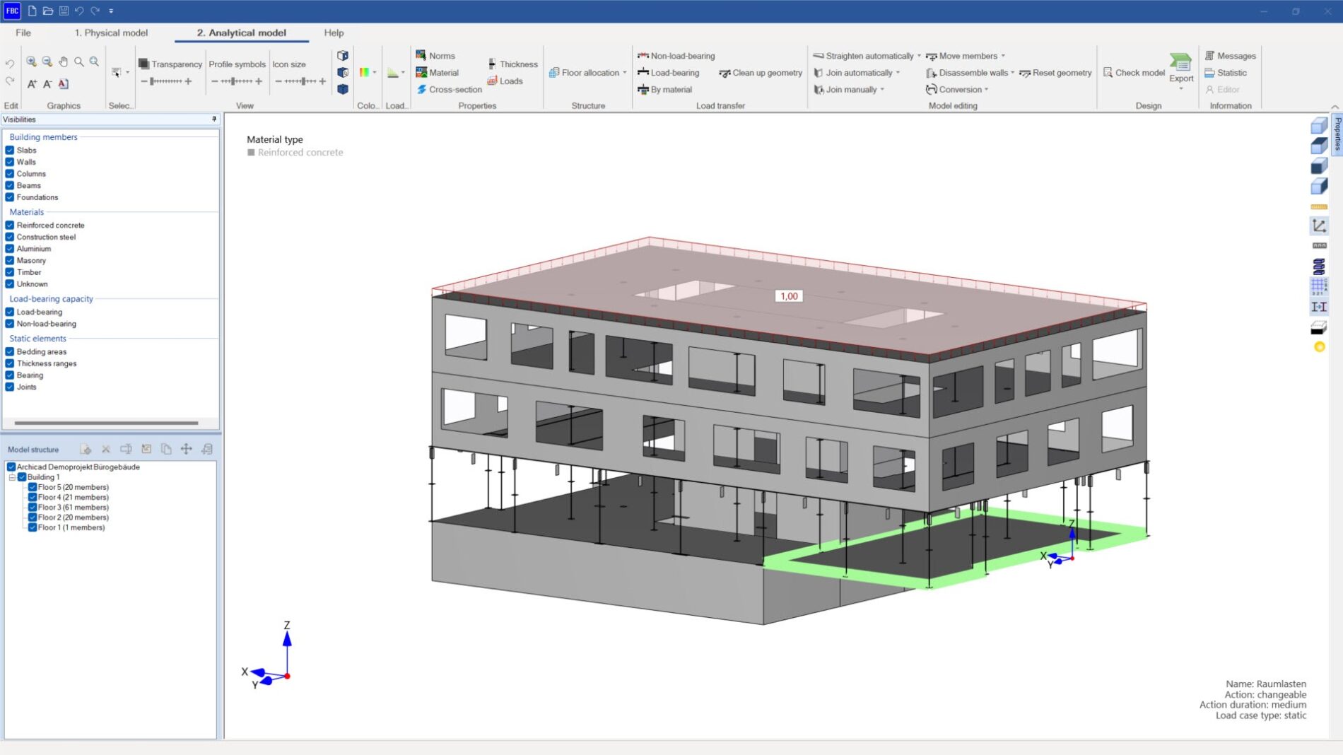
FRILO & SEMA
Bracing calculation of timber buildings
The updated FRILO 2024-2 version allows users to import a model created in SEMA as an IFC file into the BIM-Connector. SEMA is a CAD/CAM software for timber construction. The timber building can be transferred to the GEO Building Model within the FRILO environment for the determination of wind loads and the bracing calculation. Once the bracing loads have been saved intermediately, they are transmitted back to the BIM-Connector. Subsequently, individual walls can be transferred with the bracing loads and the geometry of the wall (post spacing, material, panelling) to the Timber Wall Diaphragms program HTW+ in order to design them there.
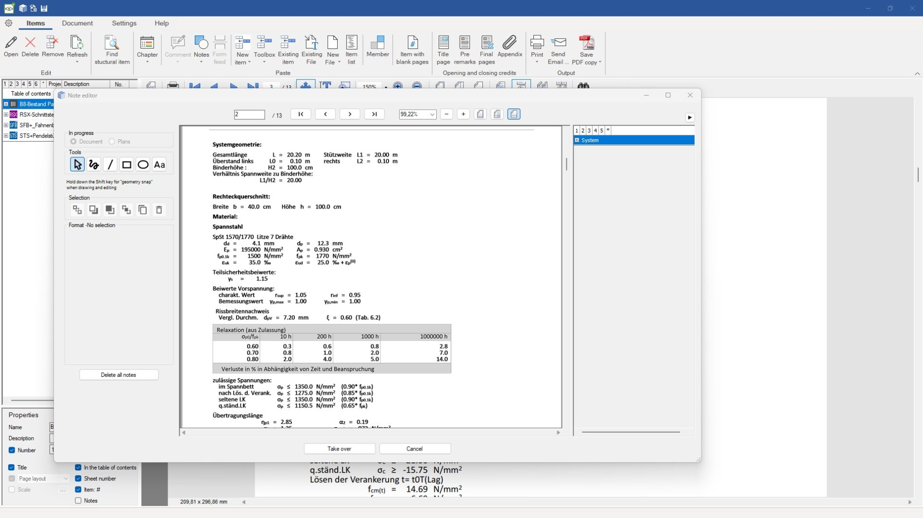
Document Designer FDD
Integration of DC items
To ensure a standardised and verifiable structural analysis document with calculation results from FRILO and DC programs, users can now also import existing DC items into the FRILO Document Designer. In FDD, users will also be able to optionally select whether they want to insert files with or without headers and whether they want to retain or discard the scaling when replacing PDF files. When saving the output document as a PDF file, users can identify and filter the various page formats.
Document Designer FDD
Note editor for FRILO and DC items
With version 2024-2 of the FRILO Document Designer, users can add user-defined text and character elements to the output document of the structural analysis in the new note editor. It allows users to apply comments and marks to FRILO items, which are still not directly editable in the Document Designer. The entered comments can be enabled and disabled as required. Another innovation: From the VCmaster 2025 application, *.hed files can be read into the FDD.