FRILO
2025
All updates and new features in FRILO 2025 and FRILO 2025-2
FRILO 2025 boasts numerous new features and program updates in the areas of concrete, timber and steel construction as well as foundation engineering. These include:
- the new PLUS program SLS+ for designing splice connections
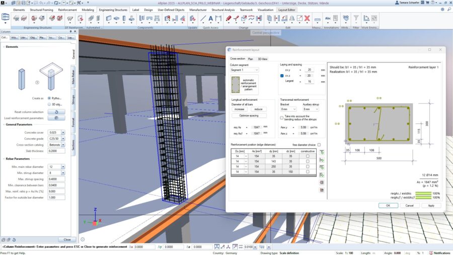
- the new reinforcement workflow for concrete columns with ALLPLAN
- the dimensioning of transverse joints to timber beams in HO12+
- the simulation of partial core failure of the timber beams in HTV+
- the graphical display of the support reactions in DLT+
- the structural analysis and design of aluminum beams in DLT+
- the design of rectangular and circular cross-sections with free point reinforcement in B2+
- new design options for mast foundations in FDM+
- the effect of partial distributed loads on the panel in RSX
- the connection of BIM-Connector to BIMPLUS
Concrete

Timber

Steel & RSX

Foundation Engineering

DLT+

FCC, FBC & FDD
B5+, B7+, B9+, B10+ and DLT+
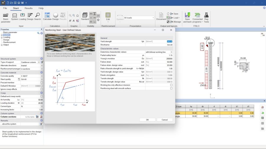
Customized concrete and reinforcement steel
With the 2025-2 version, user-defined concrete and reinforcement steel can be taken into account in the structural analysis and design of columns, continuous beams, stair flights, reinforced concrete corbels and reinforced concrete half joints. In that way, historical building materials, which often have reduced strength properties than today’s materials, can be considered in the design according to Eurocode. In addition, the partial safety factors on the material side can be adjusted as needed. Once a user-defined material has been created, it can be saved and used in the other programs that support this functionality.
Reinforced Concrete Column B5+
Reinforcement export to ALLPLAN
With FRILO 2025, users of the Reinforced Concrete Column B5+ program will be able to use a new reinforcement workflow between FRILO and ALLPLAN. A reinforcement pattern determined in B5+ for a reinforced concrete column can be transferred to ALLPLAN. Using the transferred reinforcement data, the reinforcement can be placed in the corresponding column in the CAD software with a mouse click. The data transfer from FRILO to ALLPLAN takes place via BIMPLUS and is achieved with the help of an unique IFC ID.
Verification of Reinforced Concrete Cross-Sections B2+
Documentation of stresses and strains for fire protection design
In FRILO 2025-2, the fire protection design in B2+ has been extended to include the optional graphical documentation of stresses and strains in the cross-section. In addition, the structural analysis and design of effective stiffness when determining the stresses and strains in the concrete and reinforcement steel is now also available as an option for fire protection design.
Verification of Reinforced Concrete Cross-Sections B2+
Design with free point reinforcement
The new FRILO version enables users to enter reinforcing steel with user-defined parameters using a bilinear or linear work line in the Verification of Reinforced Concrete Cross-Sections B2+ program. In addition, the design of rectangular and circular cross-sections is now possible, considering an exact reinforcement arrangement. The reinforcement dialog, in which the result is integrated, also allows free reinforcement drawings without corner bars. In addition, the fire protection design can be carried out with FEM (TA) for rectangular and circular cross-sections in the accidental design situation.
Slabs by Finite Elements PLT
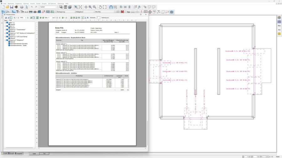
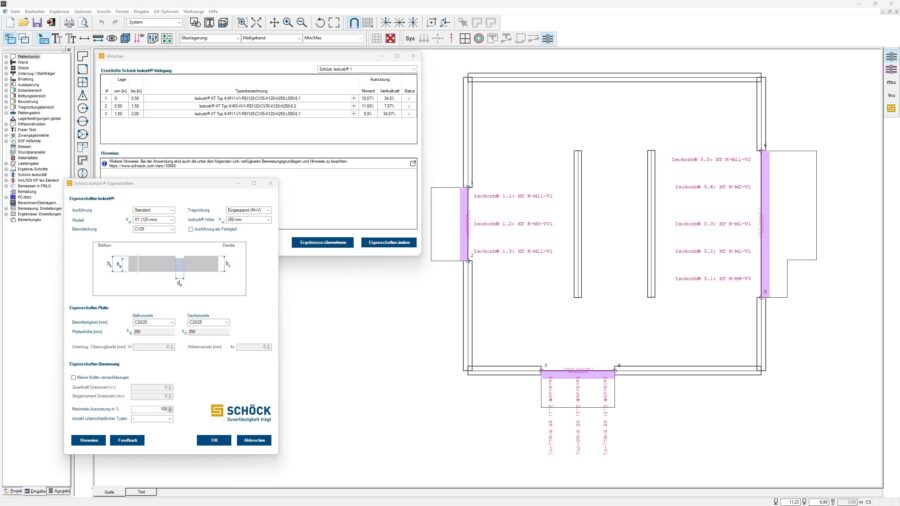
Complete parts list for Schöck Isokorb®
The output for dimensioning the Schöck Isokorb® has been expanded to include a complete parts list. The clear list contains information on the product type, article number, number of parts and linear meters of all Isokorb types used in the items. In addition, the label text of the Isokorb now recognizes any overlaps and automatically switches to the other side for better readability.
Slabs by Finite Elements PLT
Schöck Isokorb® as a prefabricated element
With FRILO 2025, PLT users can now select the Isokorb as a prefabricated element in the settings. In this case, the Isokorb design is carried out in the Schöck Scalix design program developed by Schöck, taking the K-F Isokorb types into account. Schöck Scalix is directly connected to FRILO PLT via a web interface.
Timber Construction Details HO12+
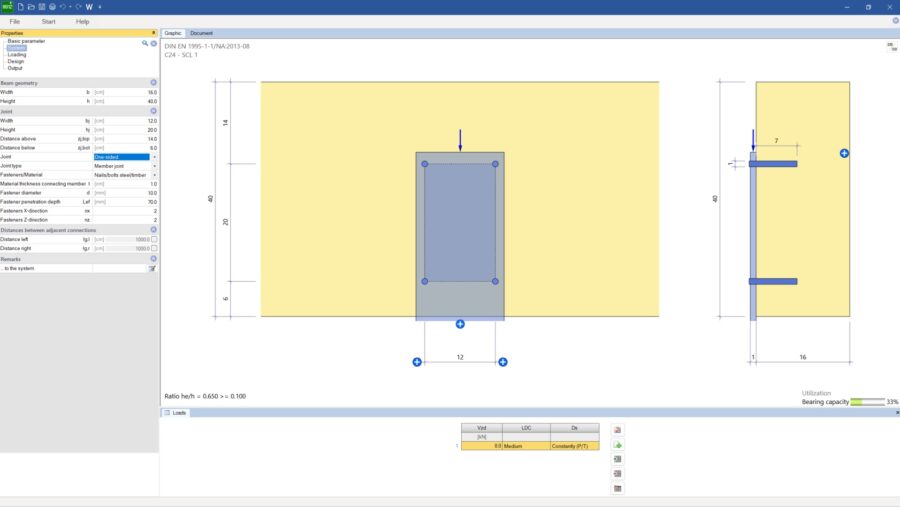
Dimensioning transverse joints to timber beams
Previously, the HO12+ Timber Construction Details program could only be used to dimension and calculate notches and breakthroughs in timber beams. With version 2025, users are now also able to take one- and two-sided transverse joints to timber beams into account in the system. Member connection or joist hanger can be defined as the connection type. Nails/bolts, dowels/bolts and connector joints are also available as fasteners for steel to timber and timber to timber. In addition to glued-on splices, glued threaded rods, fully threaded screws and SPAX fully threaded screws can be selected as reinforcement types. The HO12+ automatically checks the input of the transverse tensile reinforcements for a reasonable arrangement.
Reinforced Timber Beam HTV+
Simulation of partial core failure in the system
When designing lateral reinforcements, users can use version 2025 to define areas along the timber beam in which a partial core failure of the timber beam is to be simulated. This area can be defined multiple times in freely selectable lengths per beam. The system must be stable through the reinforcements. The core failure is also taken into account in the graphical representation of the results.
Reinforced Timber Beam HTV+
Graphical representation of the fastener forces
Previously, the results of the internal forces, deformations and utilization of all members, including the bearing stress, could be graphically displayed in the HTV+ program. For a better overview, users can now also display the fastener forces graphically. The internal forces of each individual fastener and the resulting utilization per side are visualized.
Splice Connection SLS+
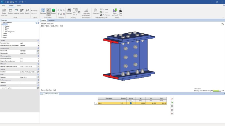
Design of Splice Connections
With the new PLUS program SLS+ Splice Connections, users can design single-axis stressed bolted girder joints with splices. SLS+ allows structural engineers to define splice connections that are characterized as rigid, flexible and hinged. DIN EN 1993 is available for dimensioning with German and Austrian national annexes. In addition to entering several load case combinations, different cross-sections and steel grades can also be defined for each member. Furthermore, it is possible to define different bolt sizes and strengths as well as different arrangement of the bolts in the respective splices. A beam offset can be specified between the member on the right and left.
Framework RSX
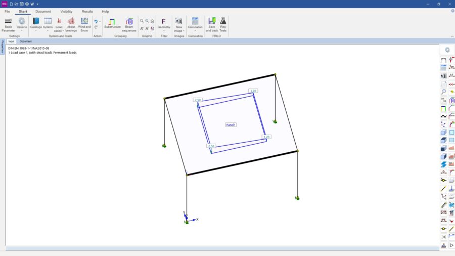
Partially distributed loads on the panel
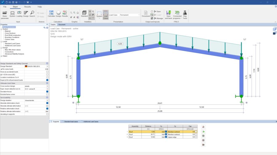
The panel function enables users of the Framework RSX program to define distributed loads and distribute them across the members. Previously, only a fully distributed load could be entered on the panel. With FRILO 2025, it is now possible to also consider the effect of partially distributed loads on the panel. In addition, the definition of variable distributed loads (trapezoidal load, triangular load) has been enabled, which means that, for example, the load area of a snow drift can be mapped.
Framework RSX
Improved documentation with automatically created images
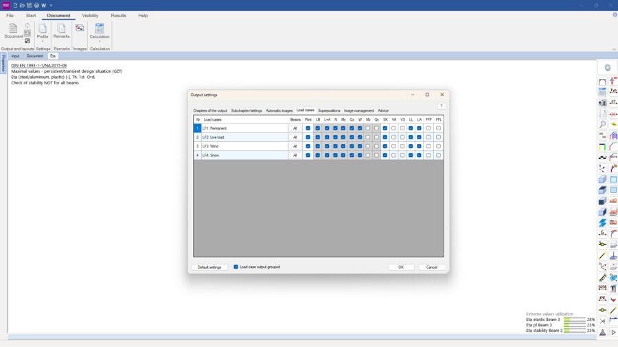
Previously, RSX users had to create all images of the results in a user-defined manner. With the new version FRILO 2025-2, both images of the system and the results can be generated automatically for the documentation by the program. The automated generation and selection of images is done within configuration dialog for documentation and can be checked in advance in the “Image management” tab. The properties of the images are set exclusively in the “Automatic images” tab.
Mast Foundation FDM+
Biaxial design
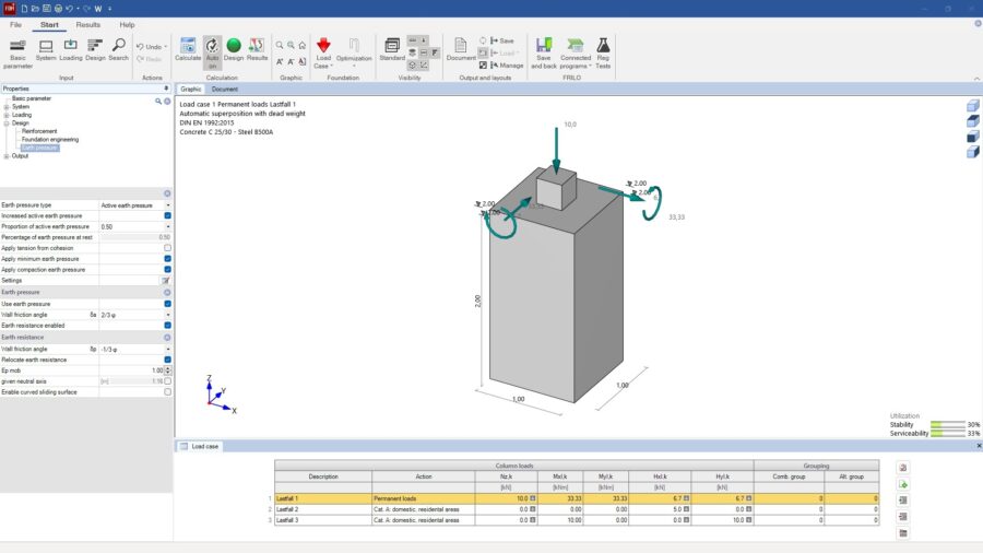
When entering mast foundations, users can now also consider a four-sided terrain definition, a groundwater level and several soil layers. In addition, a biaxial design has been added so that in the case of combined loading in the x and y directions, all relevant design directions are evaluated once separately and once as a resulting design direction. The earth pressure and forces as well as the internal forces and the associated neutral axis can be viewed as a graphical result preview and output in the documentation of the results.
Mast Foundation FDM+
Extensive earth pressure definitions
When designing mast foundations with FRILO 2025, users now have access to extensive earth pressure definitions. Active earth pressure, any increase in active earth pressure, earth pressure at rest, compacted earth pressure and earth resistance can be used. The application of the decisive earth pressure on the active and passive side is automatically selected according to the resulting loads. If necessary, the foundation is evaluated separately along all foundation edges to determine the highest load.
Slope Failure Analysis BBR+
Defining partial safety factors
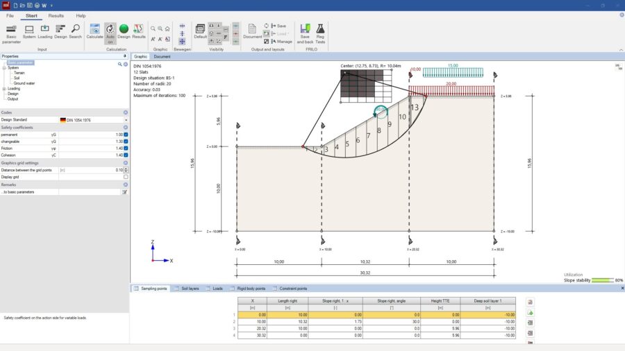
Users can now adjust the partial safety factors for the actions and the geotechnical parameters in the underlying verification procedure for slope failure as desired. The old DIN 1054:1976 can also be selected for calculating slope failure. Additional buttons have been added to fix the movement of terrain polygons only in the horizontal or vertical direction.
Continuous Beam DLT+
Analysis and design of aluminum beams
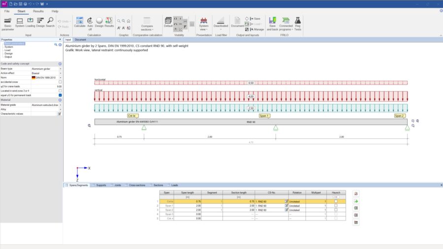
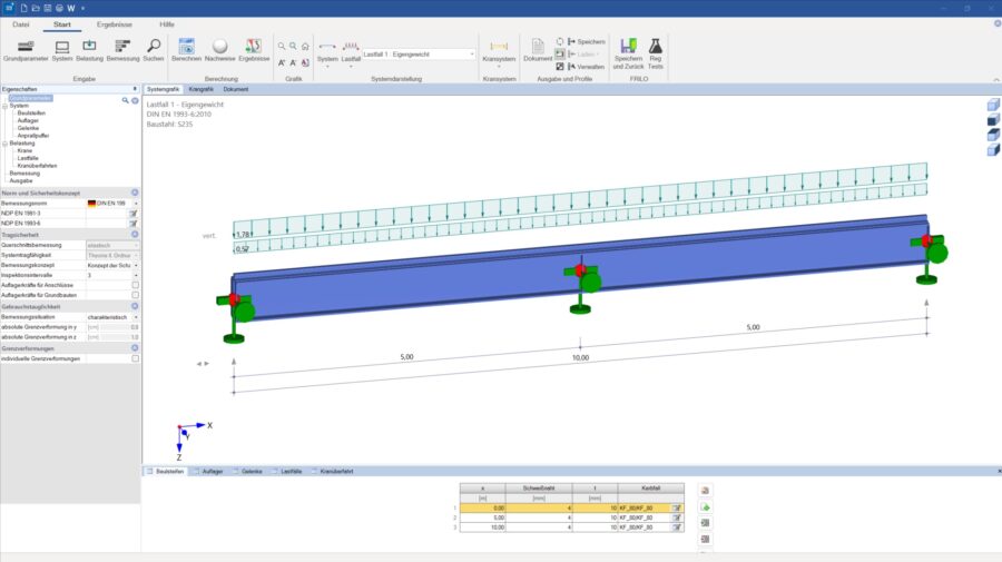
With FRILO 2025-2, users now have access to the analysis and design of aluminum beams. The design is based on DIN EN 1999. Single-span and multi-span beams with an unlimited number of spans can be calculated with or without cantilevers. Cross-sections can be constant or variable. Hinges are also possible. In addition, the design for biaxial loading is also available for aluminum beams.
Continuous Beam DLT+
Graphical display of the support reactions
With FRILO 2025, users can now also have the support reactions displayed graphically. In the results view, a graphic of the characteristic support reactions for each action group with the min/max values can be displayed. This graphic can be inserted into the documentation. In addition, the handling and stability of the reinforcement layout have been improved.
FRILO BIM-Connector FBC
Connection to BIMPLUS
With FRILO 2025-2, the FRILO BIM-Connector was connected to BIMPLUS, the cloud-based platform for data exchange and project collaboration from ALLPLAN. The seamless BIMPLUS integration allows users to optimize their workflows and collaborate more efficiently with other disciplines. Direct access to IFC and BIMPLUS models enables a smooth import of analytical models into FRILO, where the structural analysis and design is carried out.
Document Designer FDD
Faster creation of documentation
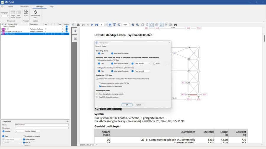
The output of the FRILO items is generated in FRILO 2025 via a newly developed interface to the output document. This means that the outputs are created up to six times faster. At the same time, the amount of data is reduced. In addition, users can now define in the FDD settings whether FRILO items and externally added files should always be included in the table of contents or not. Inactive items can also be displayed in the items view without a page header and with color highlighting.
PLUS Programs
Optimized user experience
With FRILO 2025, the PLUS program has been improved in terms of user experience at the request of users. The input table in the lower program area is now already open when the program starts. Users can also set several branches to remain expanded at the same time in the menu tree on the left side of the program interface. When switching to another input branch, the previously edited branch is not folded.
End of life of old VB6 programs
Program management
Old FRILO programs based on the Visual Basic programming language are being gradually removed from FRILO for security reasons. Superior successors in the form of the proven PLUS programs are already available for most of these programs. Subscription and SSV customers can still use the discontinued programs by installing an old FRILO version.

