Mast Foundation
FDM+
The FDM+ Mast Foundation program is used to verify foundations of all kinds of poles and towers as well as of columns for noise-protection walls, signal boards and similar structures. Mast foundations are typically block (pad) foundations that are embedded in the ground. The foundations are loaded by a moment in the first place. Their stability is ensured by the earth resistance. The serviceability and stability verifications of these foundations are performed in accordance with the subgrade reaction modulus method published in 1989 in the German Bautechnik magazine by S. Steckner. Biaxial design is possible.
Discover now more programs from the section Foundation!
SHOW MOREMaterial
- Standard concrete and lightweight concrete are selectable
- Reinforced concrete with selectable concrete qualities and steel grades
Structural system
- Square and rectangular as well as circular foundations
- As a differentiation criterion to shallow foundations and pile foundations, the ratio of the dimensions must be in the range 2/3 < D/A <= 4 (with A = width in the loading direction and D = foundation thickness) – this must be checked manually
- Selection of the reinforcement layer for the bending design
Position of foundation:
Global position coordinates and rotation angle
Column:
– Rectangular or round column
– Column dimensions
Soil:
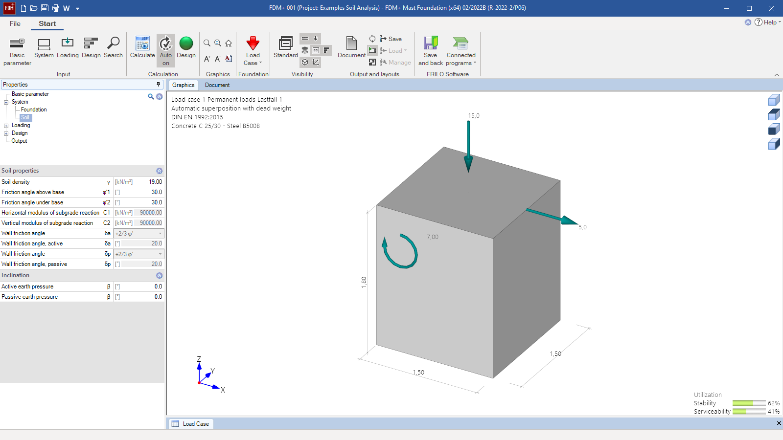
- Freely selectable soil parameters
- Subgrade reaction moduli are automatically calculated from ϕ and D
- Several soil layers can be defined
Grundwater:
Definition of a groundwater horizon
Ground surface:
- Definition of ground level above sea level
- 4-sided different terrain definition possible
- Horizontal or continuously ascending or randomly broken slope course
- Optional ground load next to the foundation
- Different embedment depths per foundation side if necessary
Loads
- Self-weight optional
- Snow exceptional
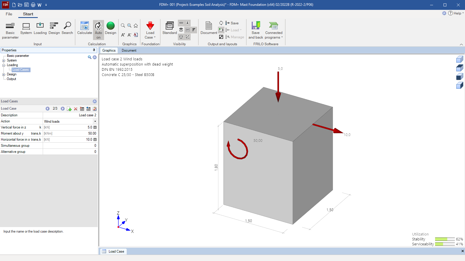
- Any loads for biaxial effects of actions:
- Vertical axial force Vz
- Horizontal concentrated loads in the x- or y-direction
- Concentrated moments about the x- or y-axis
- Free assignment of loads to types of actions according to EC 0 as well as to concurrency and alternative groups.
- Automatic combination of loads for the calculation of the decisive design load case for each verification.
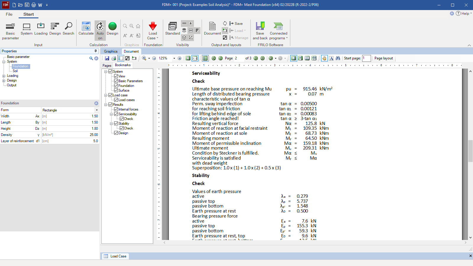
Serviceability verification
- Definition of the permissible inclination
- Serviceability verification via the inclination by means of reaction moments
Stability verification
- Definition of the safety factor for the stability verifications
- Consideration of a minimum reinforcement
- Stability verification by means of earth pressures and reaction forces via design moments
- Bending design as per selected standard
Settings
Settings for bending design:
- Minimum eccentricity
- Minimum reinforcement as compression member
Settings for reinforcement:
- Laying dimensions (sideways, bottom, top)
- Reinforcement layers (in x and y direction at the bottom and top)
- Diameter of the longitudinal reinforcement
- Diameter of the stirrup reinforcement
- Durability dialog
Settings for foundation engineering:
- Verification format “exact” or “user-defined”
- Stability verification in GEO limit state “active” or “off”
- Serviceability verification in SLS limit state (torsion verification) “active” or “off”
Earth pressure settings:
- Active earth pressure, increased active earth pressure or earth pressure at rest
- Minimum earth pressure and compaction earth pressure optional
- Wall friction angle active and passive optional
- Earth resistance with curved sliding surfaces if required
- Relocate option for earth resistance
- Mobilization factor for earth resistance optional
- Specified neutral axis optional
Document file formats
- Word
- Printer
Output
- Detailed output of the stability and serviceability with all intermediate values form the design approach by Steckner
- Output of the bending design with the required reinforcement quantity
- Graphical output of all earth pressure stresses per direction (X and Y)
- Graphical output of acting and resulting earth pressure stresses and forces per direction
- Graphical output of the internal forces curves and the sum of the horizontal forces including neutral axis for each direction
Transfer options
- Slabs by Finite Elements PLT
- Isolated Foundation FD+
- Block Foundation FDB+
- Strip Foundation FDS+
- Reinforced Raft Foundation FDR+
- Ground Failure Analysis GBR+
- Beam on Elastic Foundation BEB+
- Soil Settlement SBR+
Reinforced concrete
- EN 1992
- DIN EN 1992
- ÖNORM EN 1992
- PN EN 1992
- NF EN 1992
- BS EN 1992
- DIN 1045-1
- ÖNORM B 4700
Support resources
News
FRILO launches version 2024-2 with powerful updates for structural analysis and design
Highlights include the optimised design of Schöck Isokörbe®, the advanced integration of DC foundation engineering programs into the FRILO environment and new RSX interfaces for detail verifications in steel construction.

Load determination for eight-floor perimeter block development with FRILO Building Model
Find out how the structural engineers at bauart Konstruktions GmbH determined the loads for an eight-floor perimeter block development in Frankfurt’s Europaviertel district using the GEO from FRILO.

