
Steel Frame
The “Steel Frame” program is used to analyze and design plane steel frames. Two-hinged frames as well as restrained frames with or without cantilever are available for analysis. With just a few data entries, the user can analyze bracing frames or common substructures, for instance. It is possible to model one-bay frames with equal or different column lengths as well as half-frames.
Only available in FRILO Ultimate
Core capabilities
Material
Different materials can be selected for the individual components. The following materials are available:
- Structural steel (S235, S275, S355, S450)
- Annealed steel (S275N to S460N)
- Thermo-steel (S275M to S460M)
- Weathering steel (S235W to S355W)
- High-temperature steel (S460Q to S460QL1)
- Hollow section, hot-finished (S235H to S355H)
- Hollow section, hot-finished, fine-grain (S275NH to S460NH)
- User-defined steel
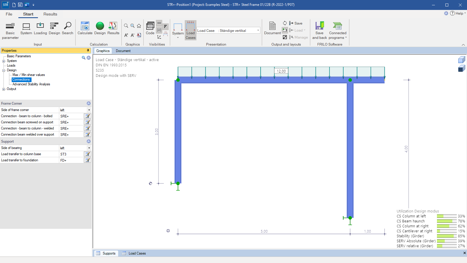
Structural system
Available systems:
- Two-hinged frame with or without cantilever(s), different column lengths can be defined
- Restrained frame with or without cantilever(s), different column lengths can be defined
- Half-frame with or without cantilever(s)
Cross-sections:
- I-sections as standard shapes
- User-defined I-sections
Supports:
- Base pinned or restrained
- Consideration of spring values for restrained and horizontally sway bases
- The user can define the frame corners with a hinge, as being flexurally rigid or by means of a torsional spring
- Intermediate restraints for cross beams and columns out of plane (rigid/spring value) are definable in addition
Loads
- Automatic consideration of the self-weight
- Concentrated load (transverse/longitudinal), moment, and line load
- Automatic generation of the load case combinations
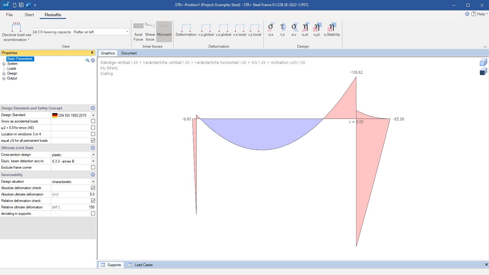
Structural safety
The program maps automatically all necessary combinations of actions in accordance with the safety concept set forth in Eurocode 0. Either the elastic or plastic cross-sectional resistance is verified. The load combinations decisive for the design are calculated in a second-order analysis with consideration of the initial sway imperfection. Furthermore, the verification of the system’s load-bearing capacity is performed using the equivalent member method either in accordance with section 6.3.3 Annex A or B or with section 6.3.4.
Serviceability
In connection with the verification of the serviceability, the program determines the deformations of the structural system as well as the relative deformations of the individual components. The user must specify the design situation that should be used for the serviceability verification.
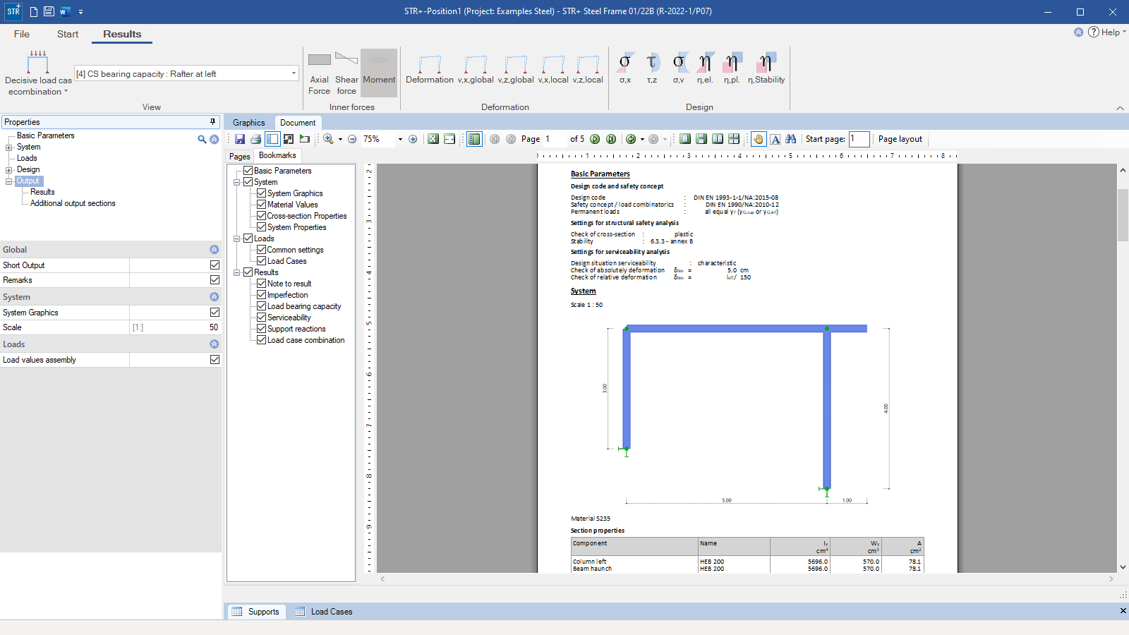
Output profile & results
Output profile:
- Pre-set abbreviated output or user-defined scope
Result graphs:
- Internal forces: N, M, Q
- Deformations: vx, vz (local or global)
- Stresses: σ,x ; τ,z ; σ,v
- Utilization Eta: n,el ; n,pl ; n,stability
File formats
- Word
- Printer
Transfer options
- Steel Frame Corner
- Lateral Torsional Buckling Analysis
- Steel Column Base
- Pocketed Steel Column Base
- Isolated Foundation
- Block Foundation
- Framework
Import options
- FRILO XML
- ASCII
Export options
- Word
- FRILO XML
- Strut-and-tie model XML
Steel construction
- DIN EN 1993
- ÖNORM EN 1993
News

Corporate headquarters as reinforced concrete skeleton structure
With the construction of a new corporate headquarters, Heidelberg Materials has demonstrated the remarkable range of reinforced concrete as an attractive building material. FRILO and Allplan were used by the structural engineers.
FRILO launches version 2024-2 with powerful updates for structural analysis and design
Highlights include the optimised design of Schöck Isokörbe®, the advanced integration of DC foundation engineering programs into the FRILO environment and new RSX interfaces for detail verifications in steel construction.