
-
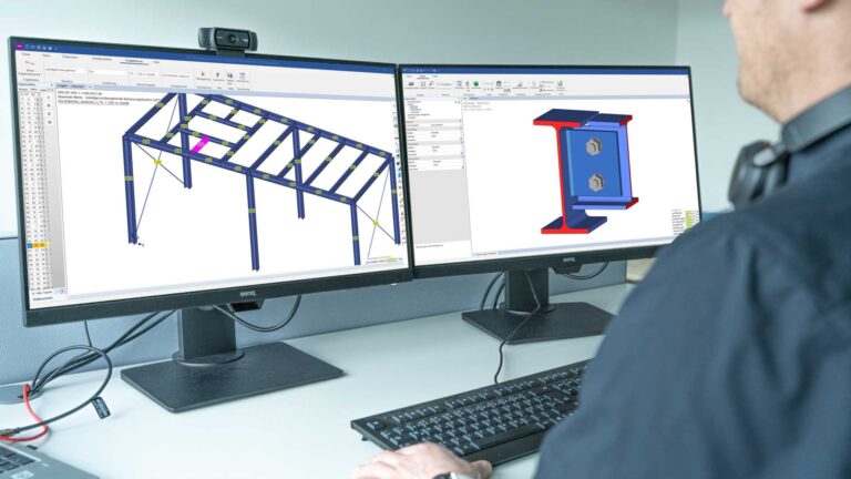
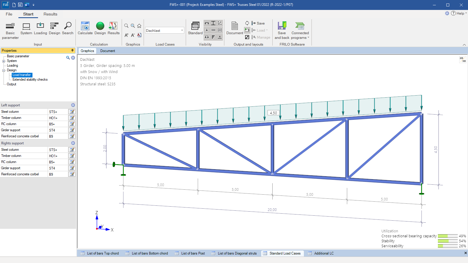 FWS+ user interface
 -
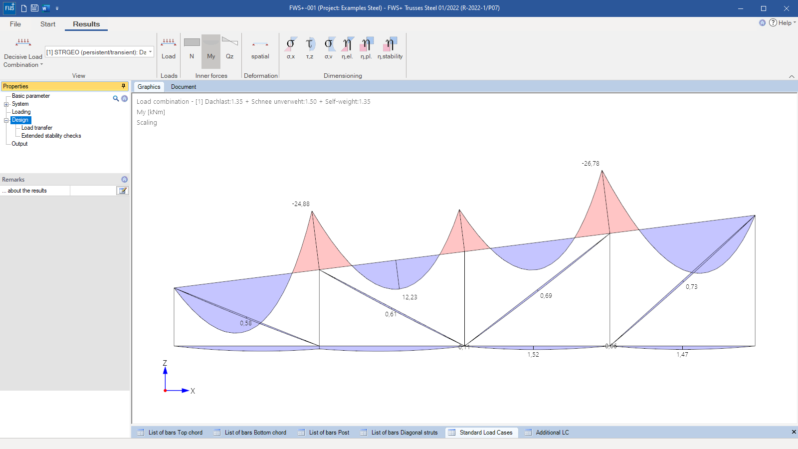 Internal forces diagrams in the results view
 -
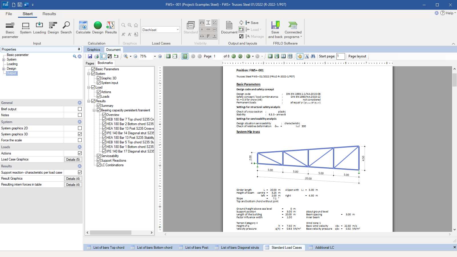 Output document
 -
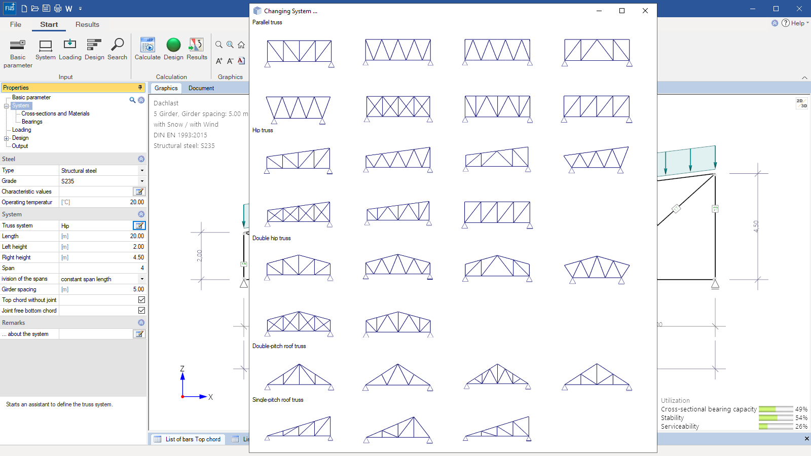 Selection options for pre-defined truss types
Trusses Steel
FWS+
The FWS+ program is used to calculate latticed steel girders and trusses typical in the construction of portal frames. Compared to the definition of the structural system and the loads in a framework program, the data entry in the FWS+ program is easier and needs considerably less time thanks to pre-defined truss types and the automatic generation of loads.
Discover now more programs from the section Steel!
SHOW MOREMaterial
Different materials can be selected for the individual components. The following materials are available:
- Structural steel: S235, S275, S355, S450
- Annealed steel (S275N – S460N)
- Thermo-steel (S275M – S460M)
- Weathering steel (S235W – S355W)
- High-temperature steel (S460Q – S460QL1)
- Hollow section, hot-finished (S235H – S355H)
- Hollow section, hot-finished, fine-grain (S275NH – S460NH)
- User-defined steel
Structural system
Available systems:
- Parallel trusses
- Hip trusses
- Double-hip trusses
- Double-pitch roof truss
- Single-pitch roof girder
- Constant symmetrical or individual span lengths
- Flexurally rigid ridge point, the top chord and the bottom chord can be free from joints
Cross-sections:
- Top chord/bottom chord: I-sections as standard shapes or user-defined sections
- Posts: I-sections, circular, square and rectangular hollow sections as standard shapes or user-defined sections
- Diagonal struts: I-sections, circular, square and rectangular hollow sections, angular, round, and flat steel as standard shapes or user-defined sections
Supports:
- Pinned support at the bottom chord
- Additional definition of supports out of plane at the top and bottom chord as well as at the vertical edge posts (rigid/spring value)
- Translational and torsional restraints on the top chord
Loads
- The loads generated by snow, wind and the self-weight of the roof skin are determined automatically with consideration of the defined building geometry. When the user changes the structural system subsequently, these loads are adjusted automatically
- The wind and snow loads are determined in accordance with the specified location of the building
- Automatic inclusion of the self-weight of the steel sections
- The user can enter user-defined load cases in addition
- Automatic generation of the load case combinations
- Concentrated load (transverse/longitudinal), moment (about the y-axis) as well as line load (transverse/longitudinal) at the top/bottom chord and edge posts
General
The program maps automatically all necessary combinations of actions in accordance with the safety concept set forth in Eurocode 0.
Structural safety
Optionally, the elastic or plastic cross-sectional resistance is verified. The internal forces are determined in a first-order analysis in this verification. Furthermore, the verification of the system’s load-bearing capacity is performed using the equivalent member method either in accordance with section 6.3.3 Annex A or B or with section 6.3.4.
Serviceability
In connection with the verification of the serviceability, the program determines the deformations of the structural system as well as the relative deformations of the individual components. The user must specify the design situation that should be used for the serviceability verification.
Document file format
- Word
- Printer
Output
Output profile:
- Pre-set brief output or user-defined scope
Result graphs:
- Internal forces: N, My, Qz
- Stresses: σ,x ; τ,z ; σ,v
- Utilization Eta: n,el ; n,pl ; n,stability
Transfer options
- Single-span Steel Column STS+
- Timber Column HO1+
- Reinforced Concrete Column B5+
- Steel Girder Support ST4
- Reinforced Concrete Corbel B9+
- Lateral Torsional Buckling Analysis BTII+
- Framework RSX
- Trusses Timber FWH+
Import options
- ASCII-file
- FRILO XML
Export options
- Word
- FRILO XML
Structural safety verifications
- DIN EN 1993
- ÖNORM EN 1993
- BS EN 1993
Wind- and snowloads
- DIN EN 1991-1-3:2019
- DIN EN 1991-1-4:2010
- ÖNORM EN 1993-1-3:2018
- ÖNORM EN 1993-1-4:2019
- BS EN 1991-1-3:2015
- BS EN 1991-1-4:2011
News
FRILO launches version 2024-2 with powerful updates for structural analysis and design
Highlights include the optimised design of Schöck Isokörbe®, the advanced integration of DC foundation engineering programs into the FRILO environment and new RSX interfaces for detail verifications in steel construction.

Load determination for eight-floor perimeter block development with FRILO Building Model
Find out how the structural engineers at bauart Konstruktions GmbH determined the loads for an eight-floor perimeter block development in Frankfurt’s Europaviertel district using the GEO from FRILO.